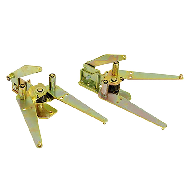
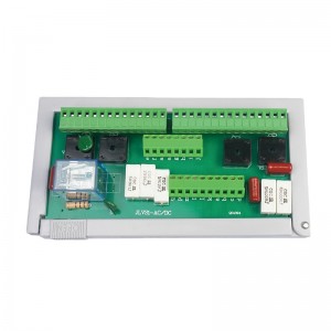
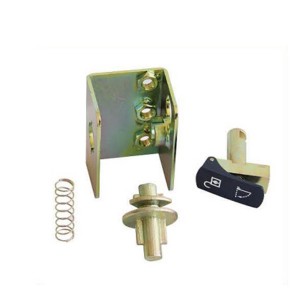
◎ Drawing of shutter mechanism device 5YF.320.010/1ZS installation drawing
Introduction
To better prolect maintenance personnel he company’s original center cabinet KYN28 shuter mechanism has been optimized to increase the self-locking function. When the handcart is pulled out of the cabinet, maintenance personnel in the maintenance, you can leave the door locked blocking the contact box and the stationary contact, avoid electrical shock caused by misuse.
Based on KYN28 switchgear, this mechanism increases self-locking function. Here is the work process. When the handcart is out of the cabinet, No.1 rotates counterclockwise around No.4 under the action of a tension spring, which makes No.3 slide to the right. And No.7 is blocked because of No.3. When the handcart is pushed into the cabinet, No.1 rotates clockwise around No.4 under the action of the handcart, which makes No.3 slide to the left. And No.7 will be unlocked and work properly.
◎(II)Drawing of valve mechanism device 5YF.320.010/1ZS installation drawing
Working Principal
● No.3 arc plate locks the No.1 rollers on the lef and right plate to realize self-interlock.
● When VCB is moving from testing position to working position, the two side pusher of the VCB will press the upper down No.3 arc plate to rotate to the middle. So the self-locking mechanism will be unlocked and the shutter mechanism will open normally.
● When VCB is out, No.3 arc plate will be pressed by No.2 tension spring to lock No.1 roller and the shutter mechanism wil be locked.
KYN28A-12(GZS) High Voltage Switchgear Fittings
◎ Drawing of shutter mechanism device 5YF.320.010/1ZS installation drawing
Introduction
To better protect maintenance personnel, the company’s original center cabinet KYN28 shutter mechanism has been optimized to increase the self-locking function.When the handcar is pulled out of the cabinet,maintenance personnelin the maintenance,you can leave the dorlocked. blocking the contact box and the stationary contact, avoid electrical shock caused by misuse.
Based on KYN28 switchgear, this mechanism increases self-locking function. Here is the work process. When the handcart is out of the cabinet, No.1rotates counterclockwise around No.4 under the action ofatension spring, which makes No.3 sideto the right.And No.7 is blocked because of No3.When the handcart is pushed into the cabinet, No.1 rotates clockwise around No.4 under the action of the handcart, which makes No.3 slide to the left. And No.7 will be unlocked and work properly.
◎ (II)Drawing of valve mechanism device 5YF.320.010/1ZS installation drawing
(II) Working Principal
● No.3 arc plate locks the No.1 rollers on the left and right plate to realize self-interlock.
● When VCB is moving from testing positlion to working position, the two side pusher of the VCB wil press the upper down No.3 arc plate to rotate to the middle. So the self-locking mechanism will be unlocked and the shutter mechanism will open normally.
● When VCB is out, No.3 arc plate will be pressed by No.2 tension spring to lock No.1 roller and the shutter mechanism will be locked


